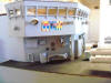
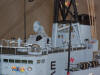
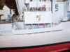
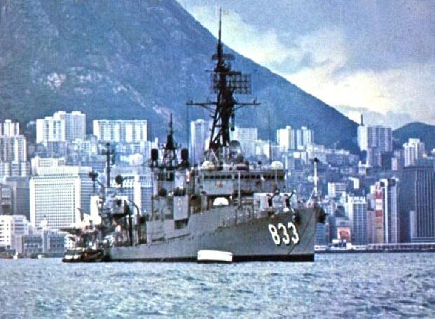
USS Herbert J Thomas in Hong Kong Harbor circa July 1969. There's
an aircraft carrier anchored behind us making the Thomas appear to
have 3 mast. The ship was built in 1945 in Bath, Maine. I served aboard
from October 68 to October 70. The ship was decommissioned in December
1970 and placed in the inactive fleet reserve until 1974 when it was
transferred to the Republic of China where is served another 25 years.
In 1999 it was sunk as an artificial reef off the coast of Taiwan.
Having built a number of reefers for Tom Miller's layout in Portland,
Oregon, I was invited to attend a VIP tour before he had his open house
for the narrow gauge convention. Tom has an impressive collection of
custom built model ships which planted the idea of making the destroyer
I was on in the late 60's. The Thomas was a gearing class destroyer.
There were 99 gearings built between 1944 and 1946. Most had minor
upgrades, namely to the radar systems in the 1950's. In the 1960's 98 of
the gearings went through a FRAM upgrade. FRAM meaning Fleet
Rehabilitation and Modernization. There was a FRAM 1 and a FRAM 2
modification. The Thomas received the FRAM 1 starting in 1964 at Mare
Island, California. The overhaul was completed in 1966. The FRAM
upgrades were to remove the old WW II weapons and replace them with
"modern" anti submarine warfare weapon systems and "state of the art"
radar systems. The ships were striped down to the main decks and all
superstructures rebuild. This time in aluminum to keep the weight down
for all the new weapons.
The Thomas was selected to receive a one of a kind FRAM re-build. It
received what was called a STOPS system. STOPS stands for Shipboard
Toxicology Operational Protective System. The hull was pressurized with
revolving doors fore and aft and double hatch pressure doors along the
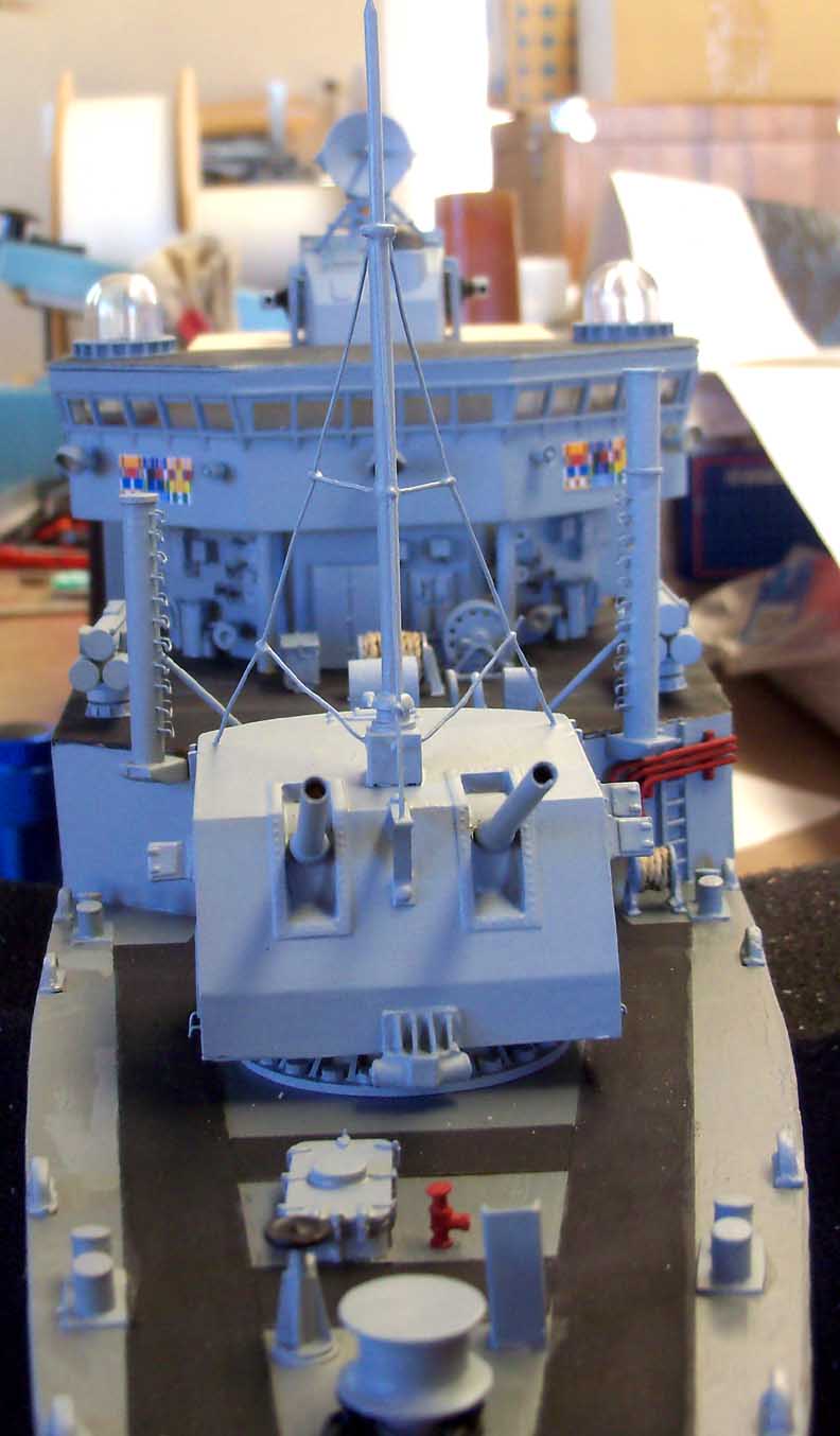
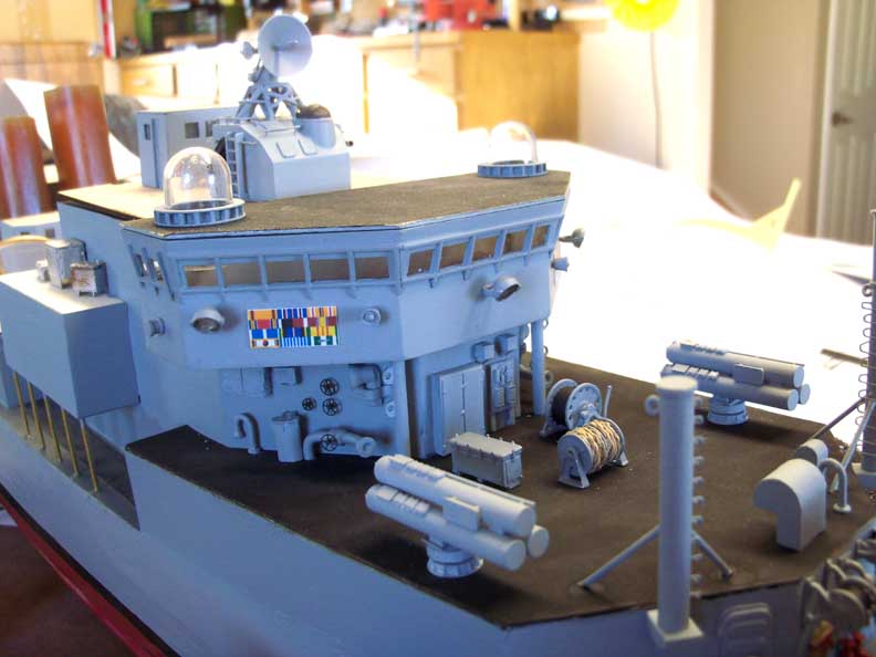
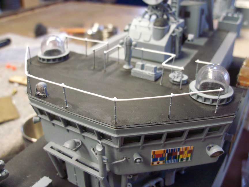
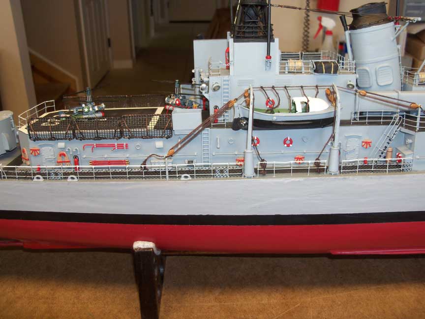
port and starboard sides and no portholes at all. If you look at the
picture, you can see glass bubbles on either side of the bridge. All
other destroyers, gearing or another class, have open bridge wings for
the lookouts. On the Thomas, the bridge was wider and closed for the
pressure system. Hence the bubbles for the lookouts. The ship had
several other changes made to the superstructure, mostly to accommodate
the STOPS build out. You can Google the ship and read about it. You will
see many sites that talk about Project Shad. Rather a sad story of what
the government did to our young men while serving their country. I won't
get into that here. I'll leave you to read about it and form your own
opinions. I made contact with Carl Ellis who served aboard a couple
years before I did. He was aboard when the ship was involved with Shad.
A couple of his friends have died from complications of those events.
Carl also built a model of the Thomas and the two of us have been
"comparing" notes of our time in the navy.
So, enough of the boring stuff, lets get going..................
Quality model ships, like our quality model trains are expensive. I did
a lot of searching and found an affordable kit manufacturer in AZ. The
company is BAD Ship Models. They have kits of the Gearing Class
Destroyers in WW II as built and post FRAM 1 modification. So in the
spring of 2012, I purchased the FRAM kit and was on my way. When I
received the kit, I found that many of the detail castings and other
parts to be a bit rudimentary for my taste. Started searching the net
and found a couple high end parts manufacturers. Namely John R Haynes,
Tom's Model Works and Scale Shipyard. Every month I sent off an order to
one of the manufactures buying replacement parts. I ended up having more
dollars in parts than the original kit. Many of the parts I had to make
as the Thomas was a one of the kind and no one was going to make parts
that only one destroyer in the whole fleet had aboard it.
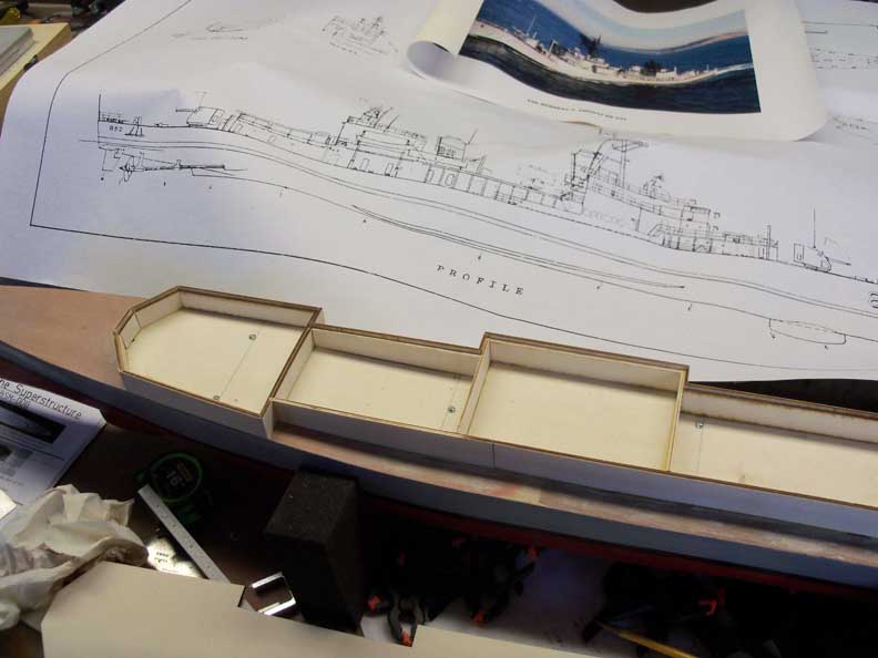
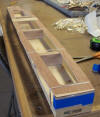
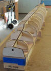
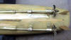
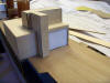
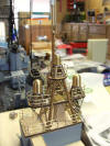
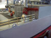
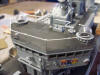
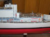
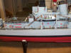
I started construction of the hull in November 2013. BAD models are a
plank on frame type of construction. The kit came with a keel and 7
frames. Well, that wasn't enough frames for a guy that builds "rugged"
1:20 scale rolling stock. I added another 14 frames to the keel. To save
room on the page, I am making the pictures a thumbnail that you can
click to enlarge and then press your back button to return.
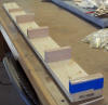
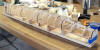

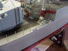
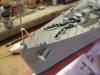
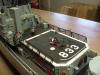
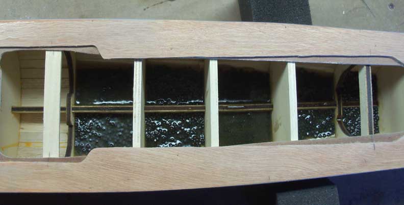
I made a frame first. Then rubber banded the sub deck to it. The frames
are glued to the sub deck after that and the balsa planks glued on. For
whatever reason, I didn't take any pictures of that process. Trust me,
it took quite a while to attached a couple hundred 1/8" by 3/8" balsa
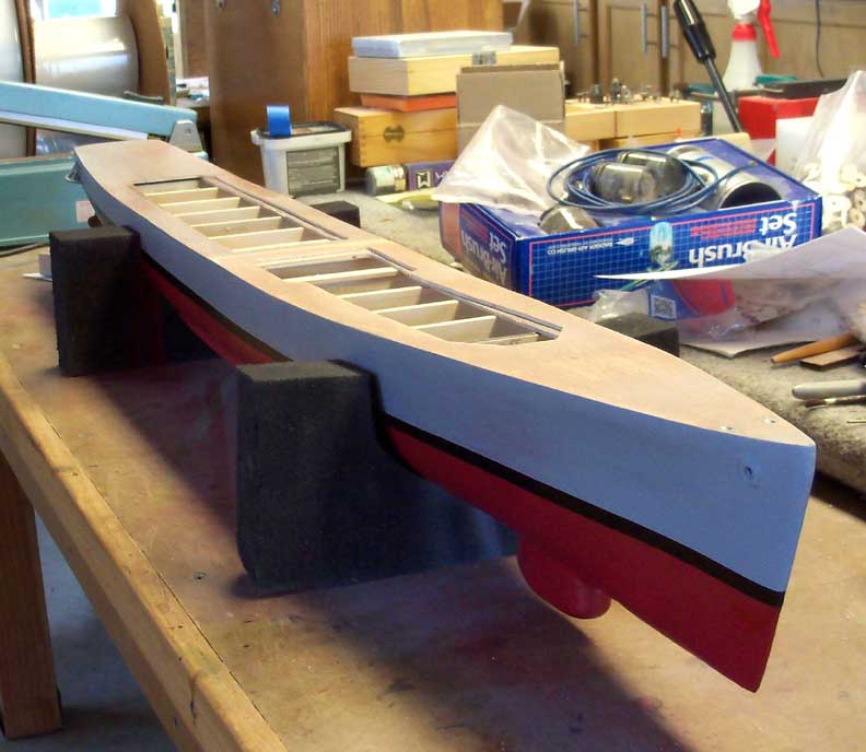
sticks. Once they were all on, I filled all the gaps with wood putty and
sanded smooth. Then added 8 to 10 coats of fiberglass resin until
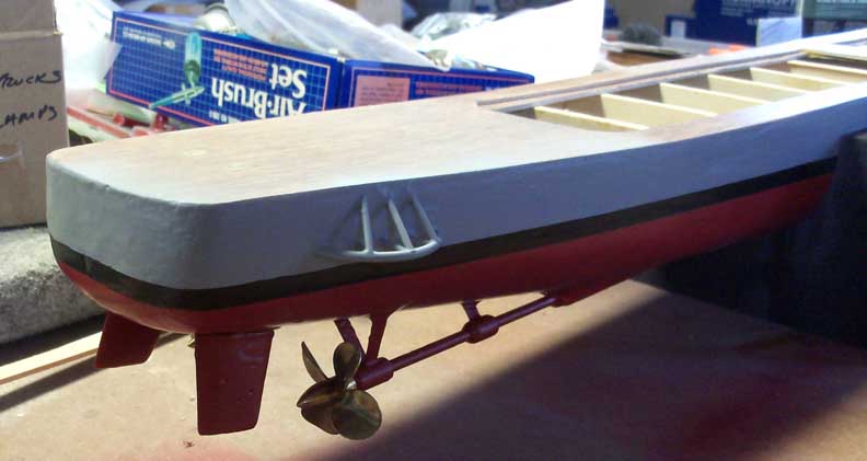
I had a thickness of about 1/8". Then I painted the hull to specs. I
added about 5 lbs of #5 lead shot between the frames for ballast.
It will never see the water but I didn't want it to be top heavy.
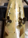
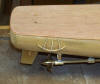
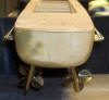
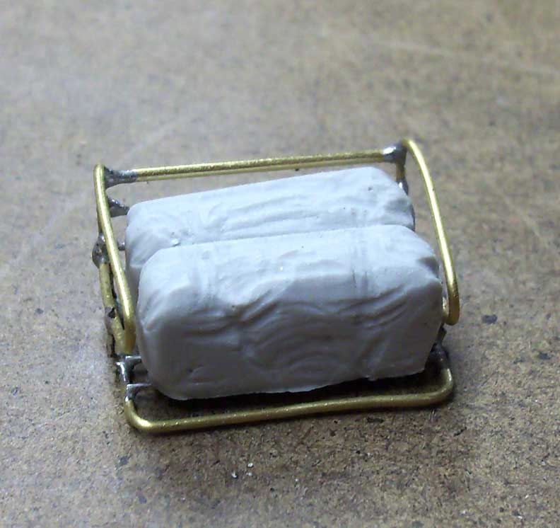
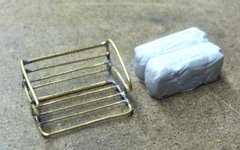
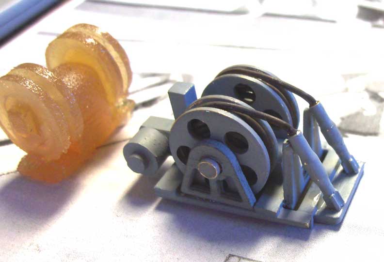
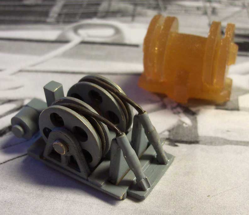
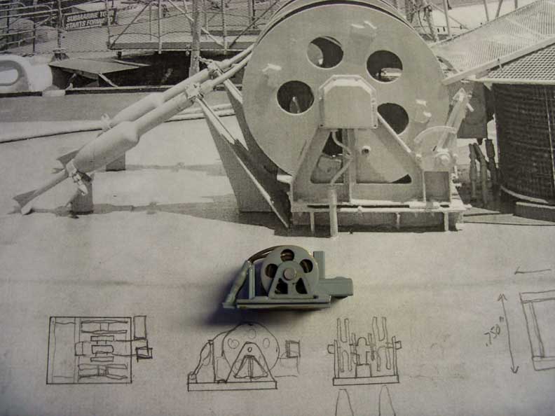
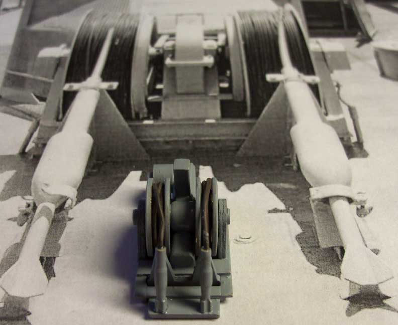
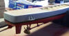
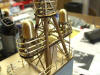
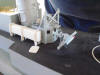
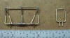
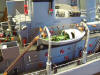
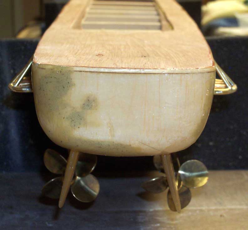
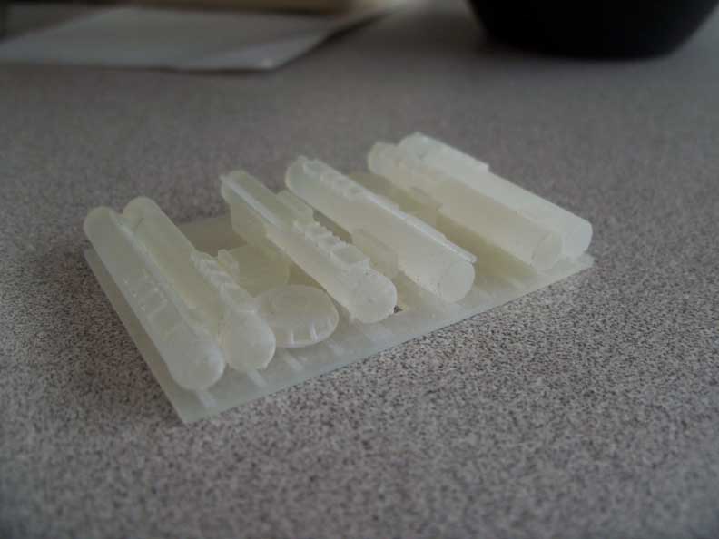
Above are pictures of the propeller guards and the running gear. The
running gear came with the kit but the prop guards that came with it
were vacuum formed to be reinforced with wood dowel. Wasn't going to cut
it with me.
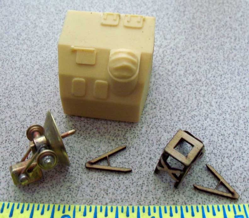
When I get to pictures of the superstructure, there'll be guns, radar
and other pieces that you'll think got magically built or they came
pre-built. So, here are pieces I made or castings from John R Haynes
that I super detailed.
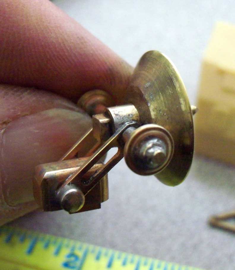
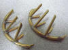
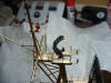
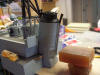
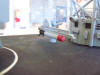
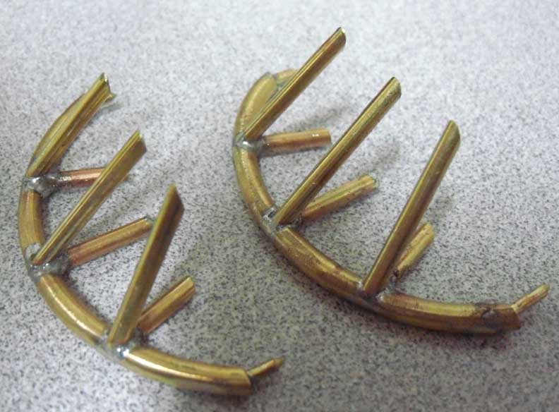
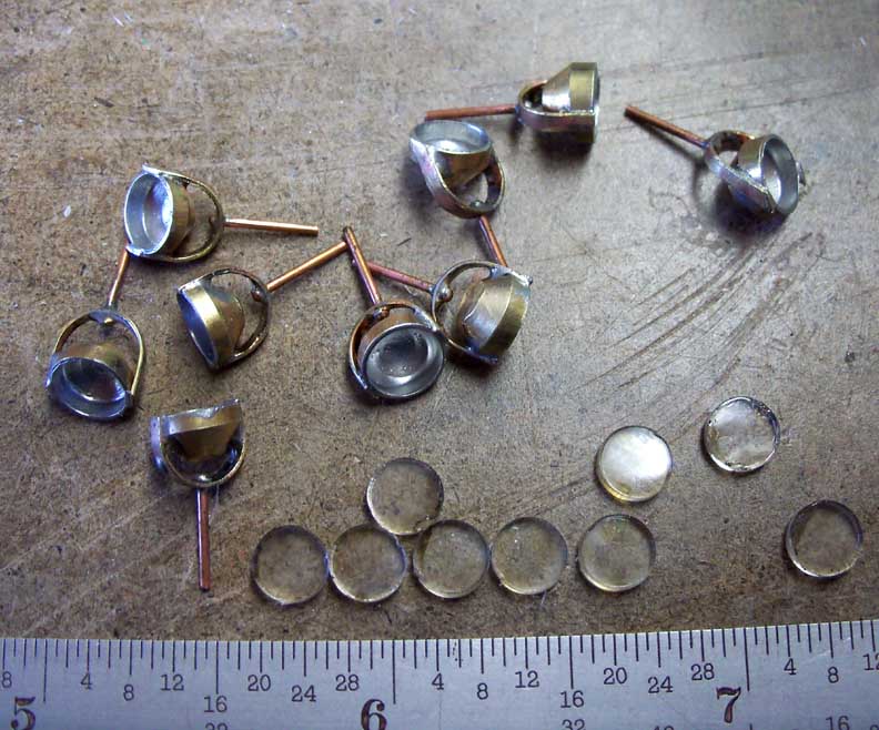
This is a T-Mark 6 Fanfare device. It was used as a noise maker that was
towed behind the ship if a noise seeking torpedo was fired at the ship.
The trailing devices had noise generators inside that would, hopefully,
draw away a noise seeking fish. Most of that type of torpedo was
discontinued by our enemies after WW II. Every non US or UK sub we
encountered was Soviet and pretty sure carried active sonar searching
torpedo's. Glad we never had to test this thing!!
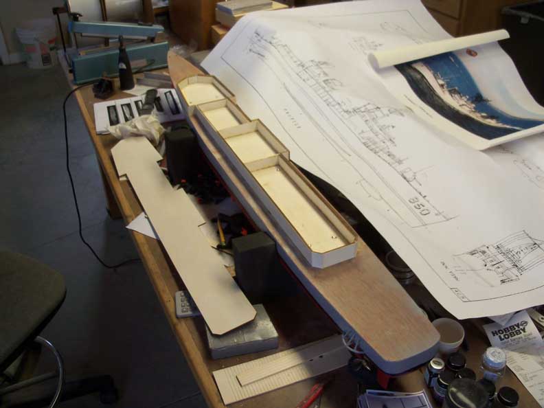
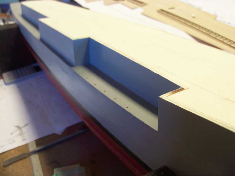
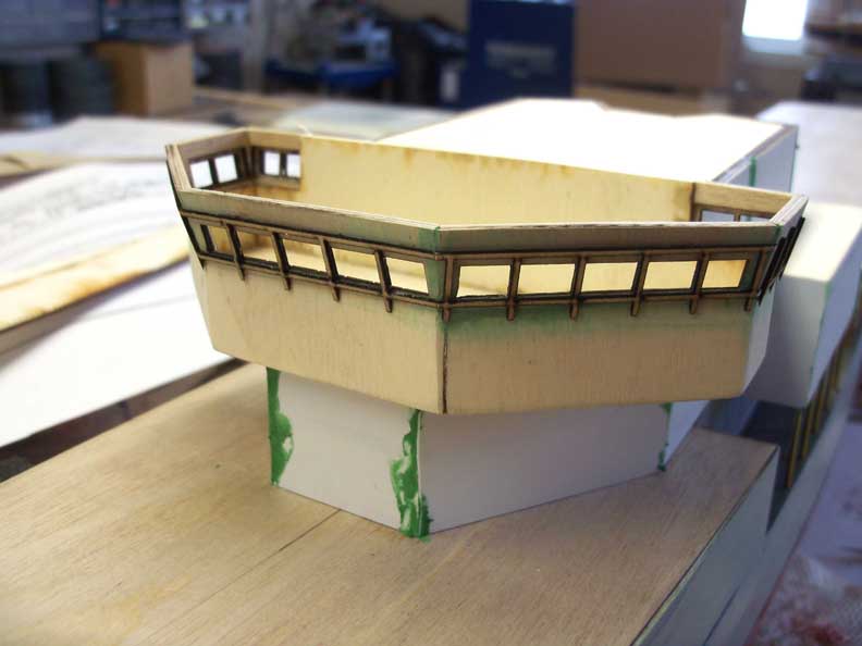
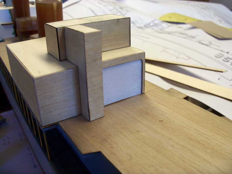
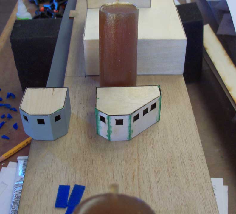
I couldn't use any of the superstructure material as the kit is based on
the USS Joseph P Kennedy DD-850. Also a gearing but very different from
the HJT (Herbert J Thomas). I use 1/8 poplar plywood for all bulkheads
and skinned it with .010" styrene. Squadron Green puttied the joints,
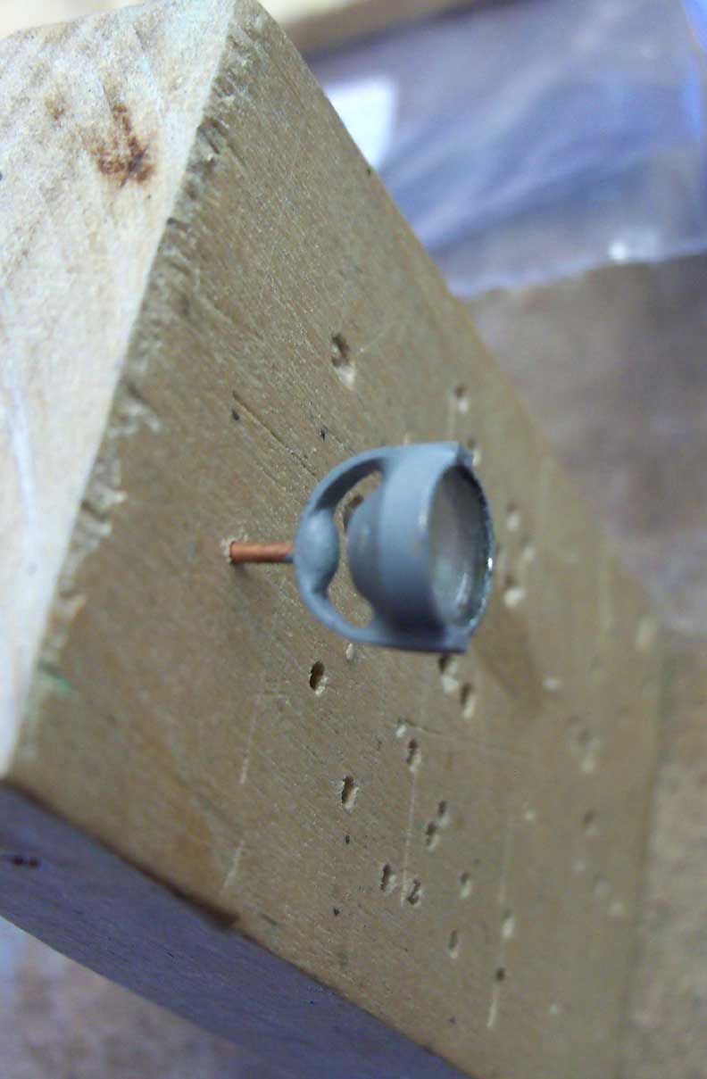
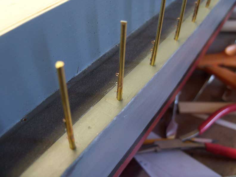
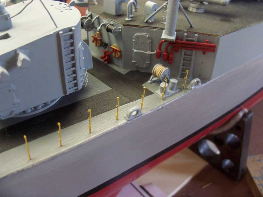
sanded and painted. The stanchions are 1/16" brass rod with etched brass
stanchions solder to them. The little eyes will support the three
stanchion cables of the main deck.
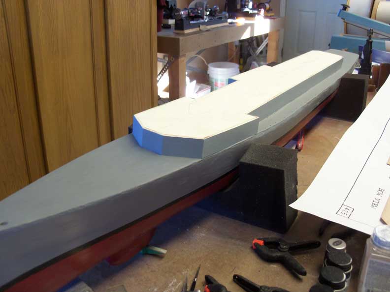
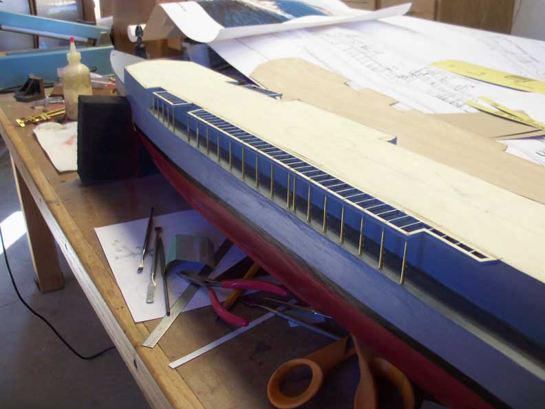
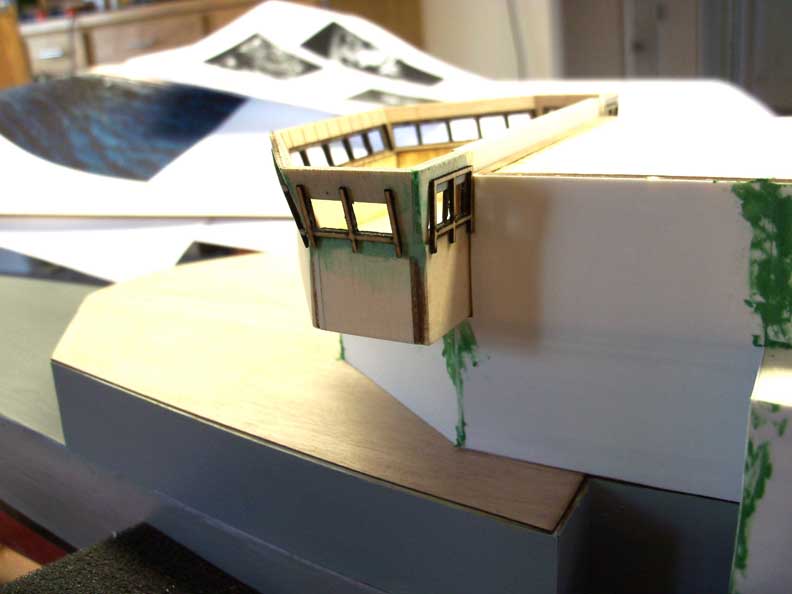
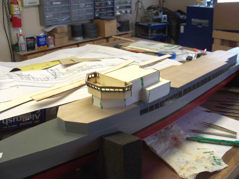
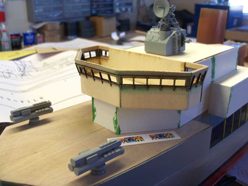
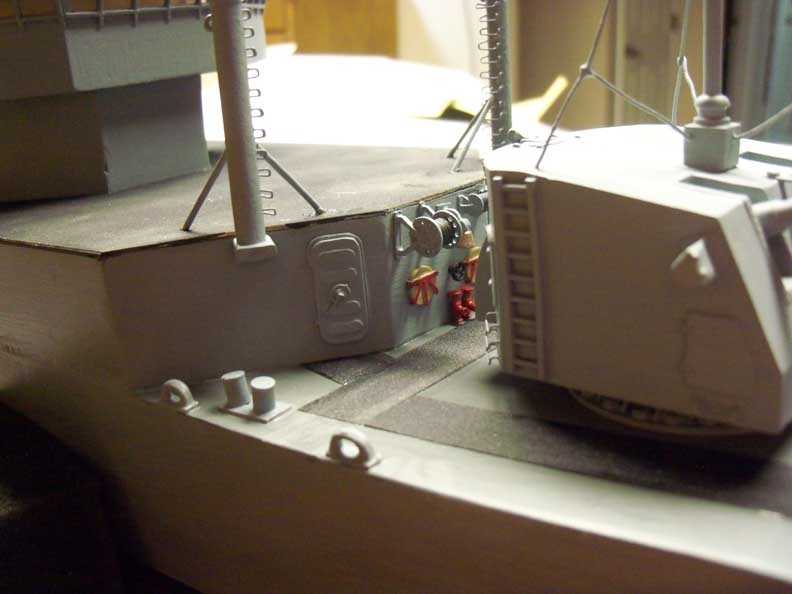
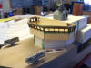
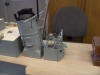
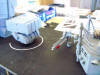
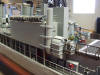
More main deck structure. The bridge is starting to come together as is
the rear structure. The orange colored castings came with the kit. Some
will get used, some not.


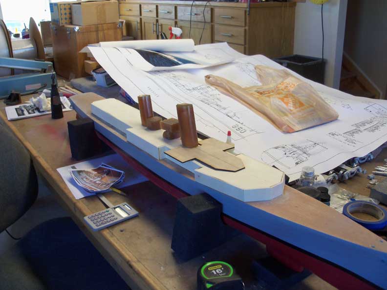
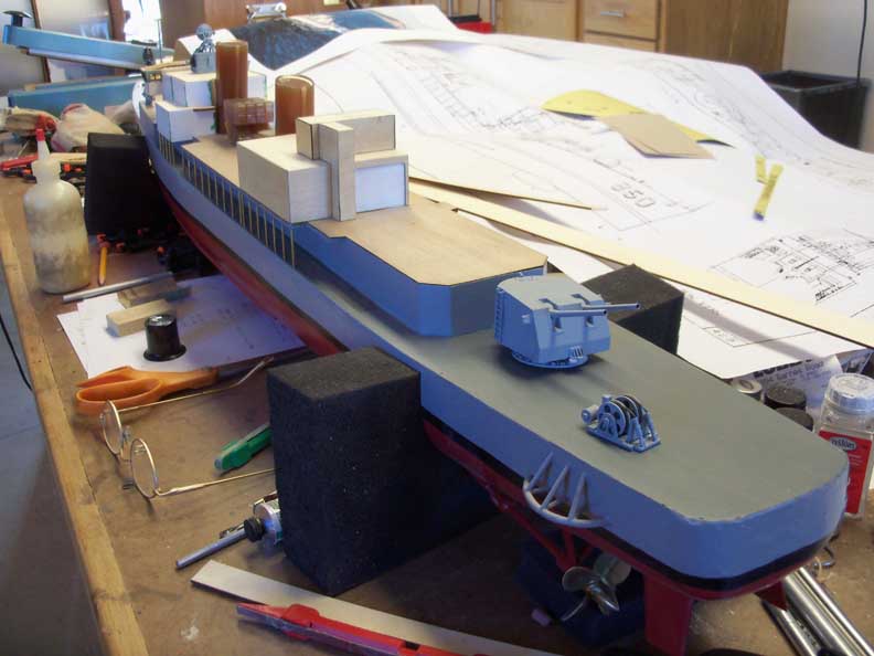
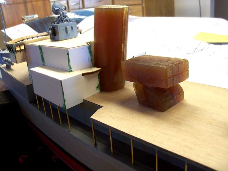
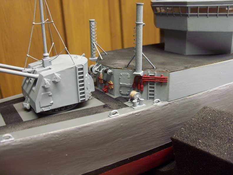
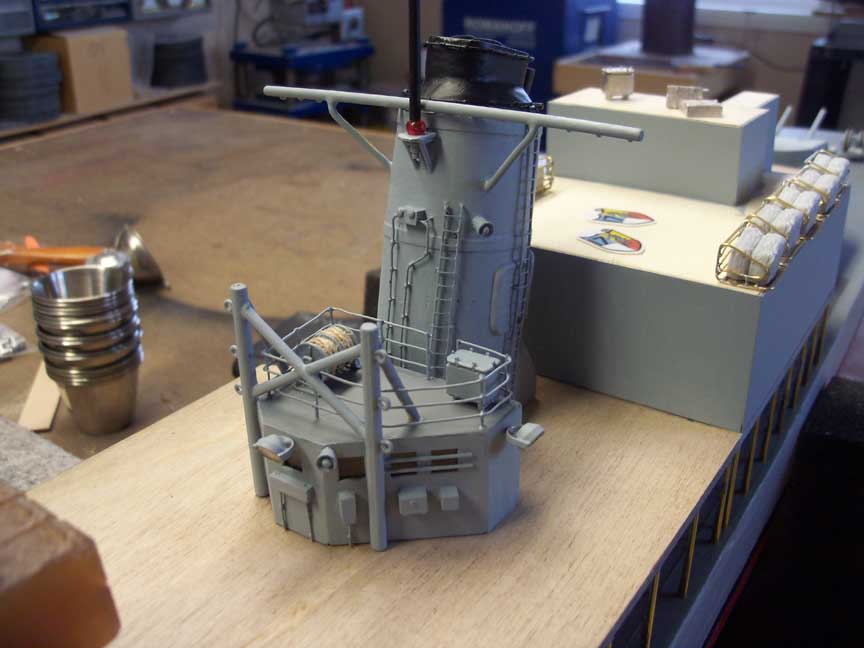
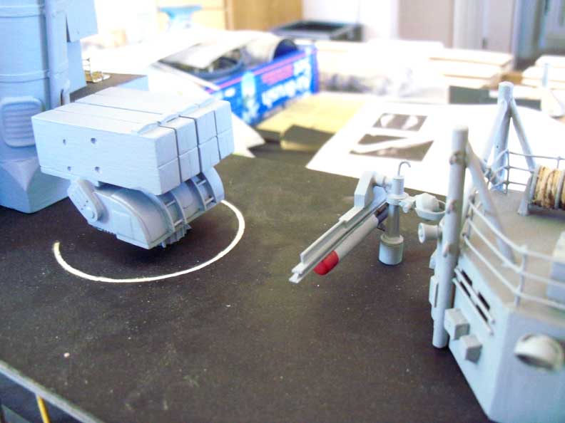
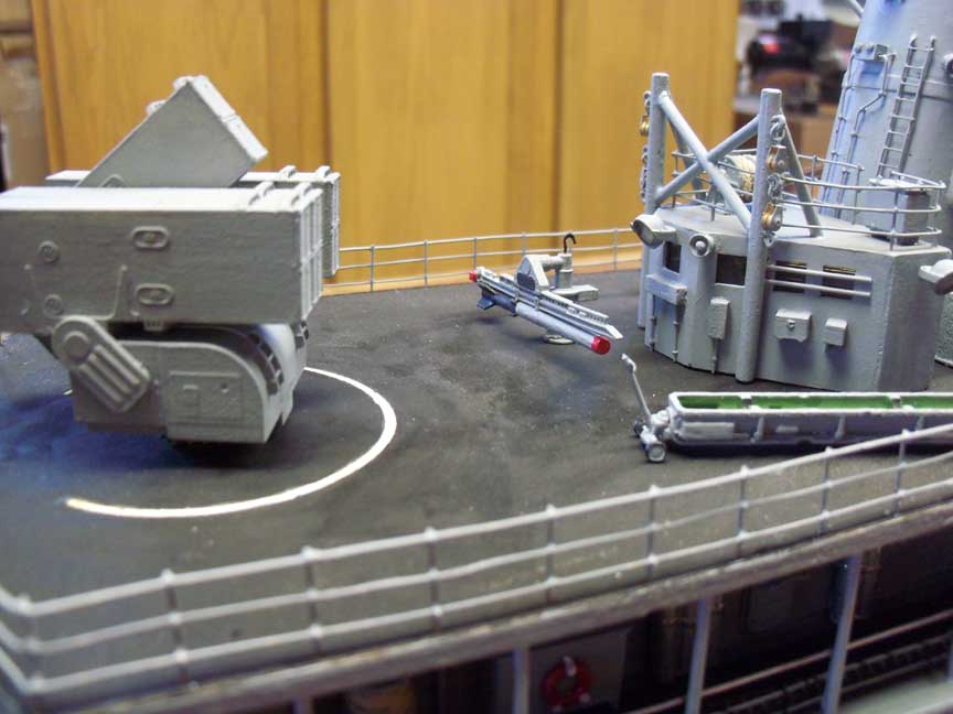
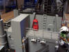
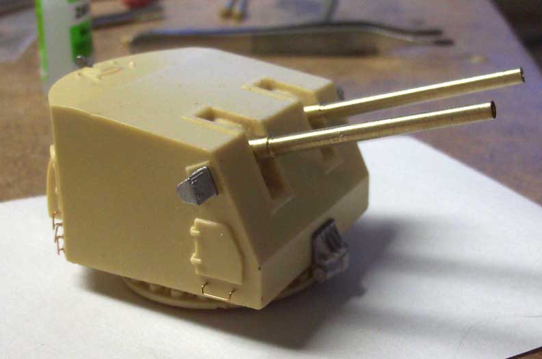
Forward funnel and ASROC launcher. ASROC stands for Anti
Submarine Rocket. We could fire a MK 44 torpedo or a nuclear
depth charge out a couple miles. Remember the saying, close only
counts in horseshoes and hand grenades? We added horseshoes,
hand grenades and nuclear depth charges. Also added is the
bridge roof with bubbles.
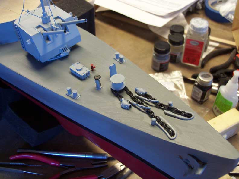
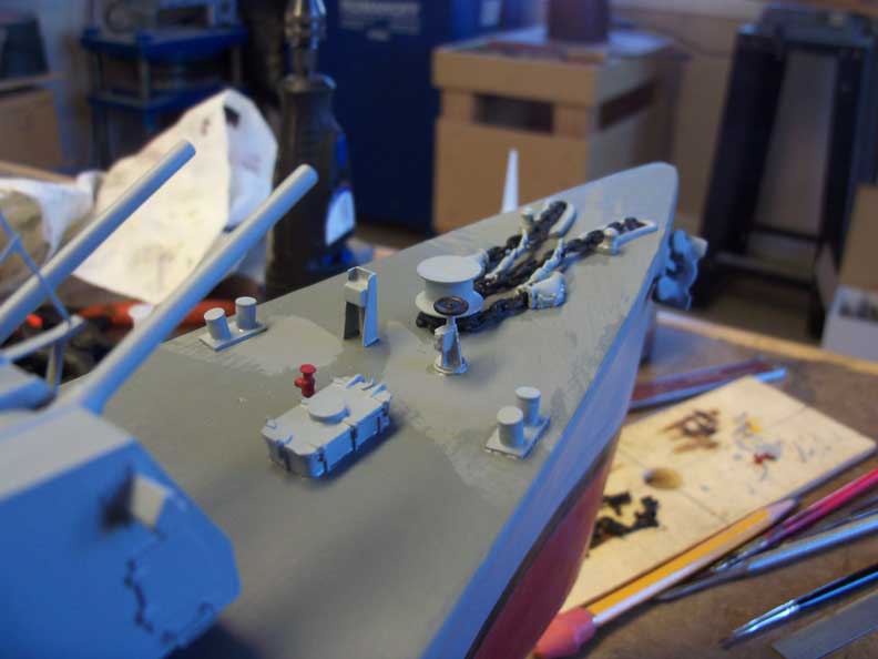
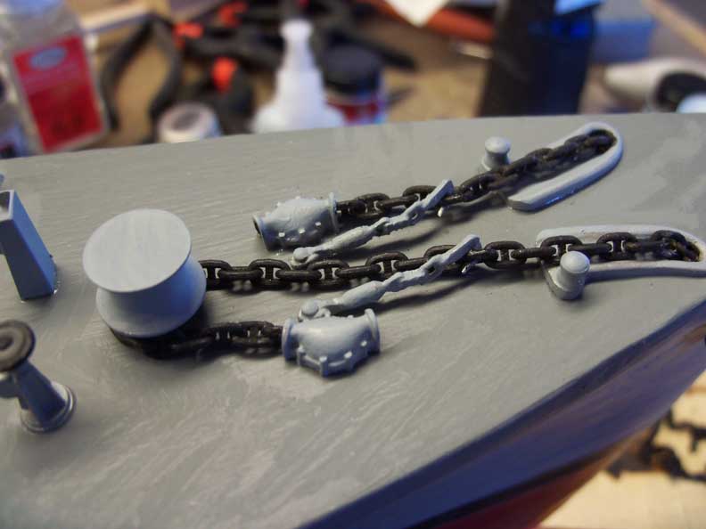
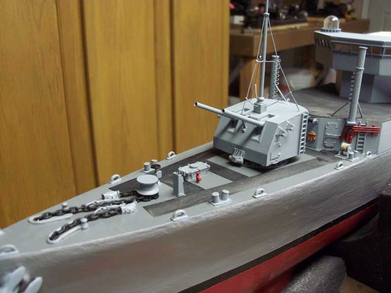
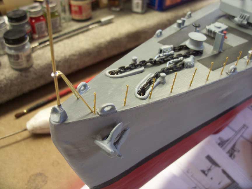
Bow detail. Most of this detail is from John R Haynes. Some of
the bulkhead detail I made.


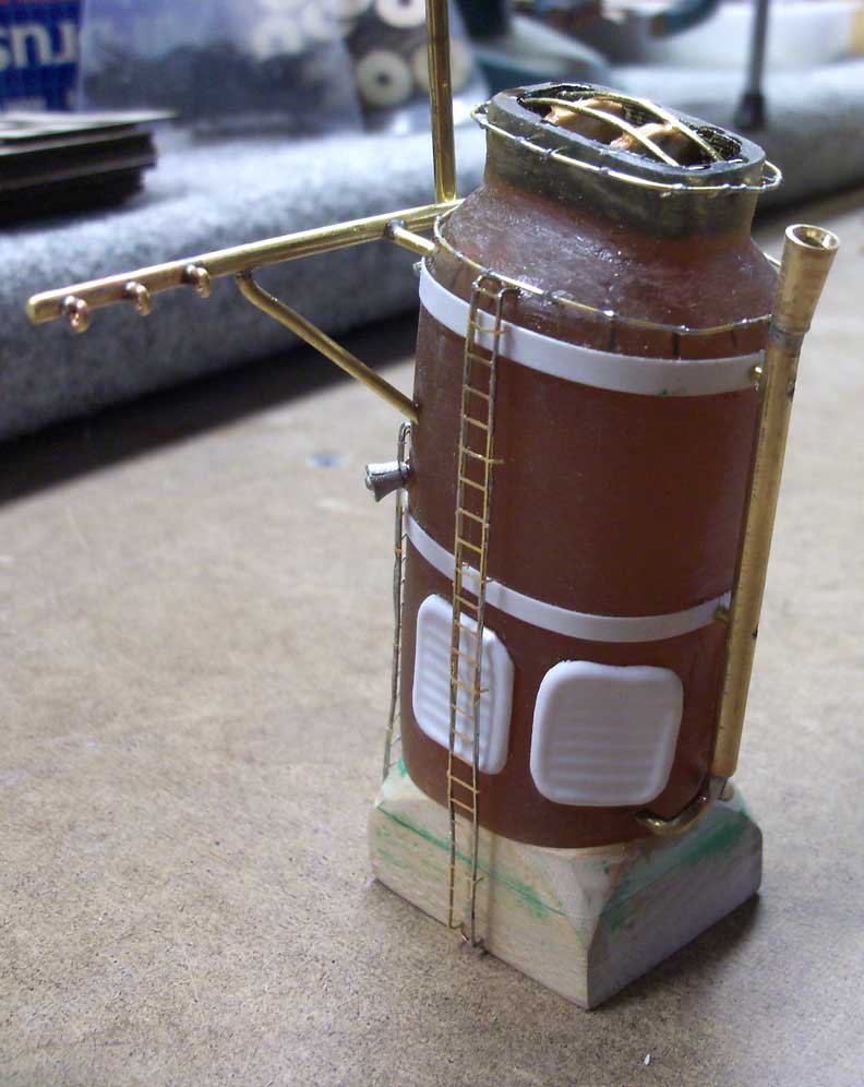
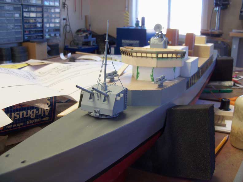
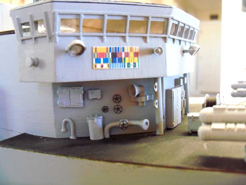
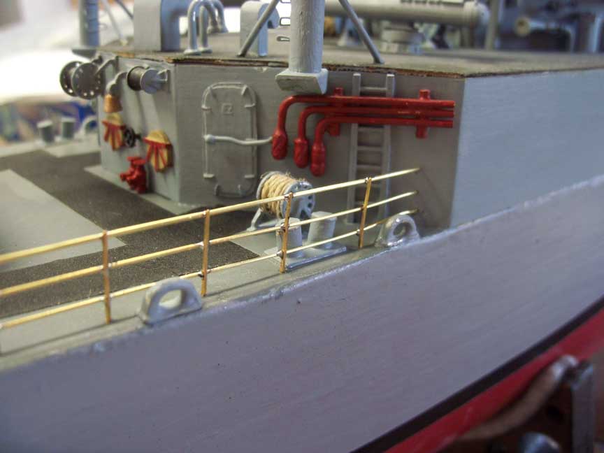
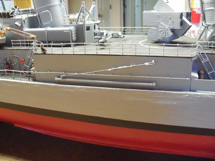
Forward view. Torpedo deck view. The plumbing under the bridge is
the forward re-fueling stations. One on each side under the bridge.
This was so we could take on fuel from either side of the ship while
underway. More times than not, we took on fuel from the port side.
Probably just the luck of the draw as we were fitted for both sides.
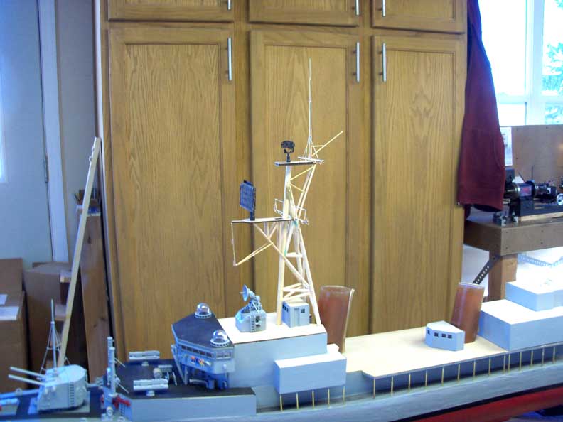
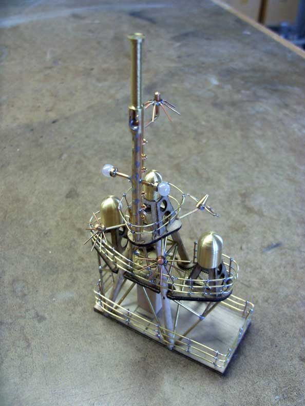
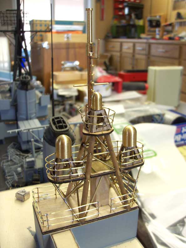
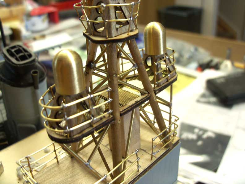
Also pictures of the bridge roof and the start of the main mast.


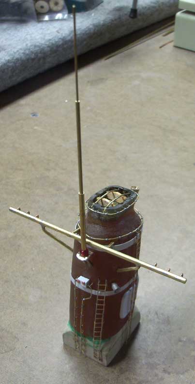
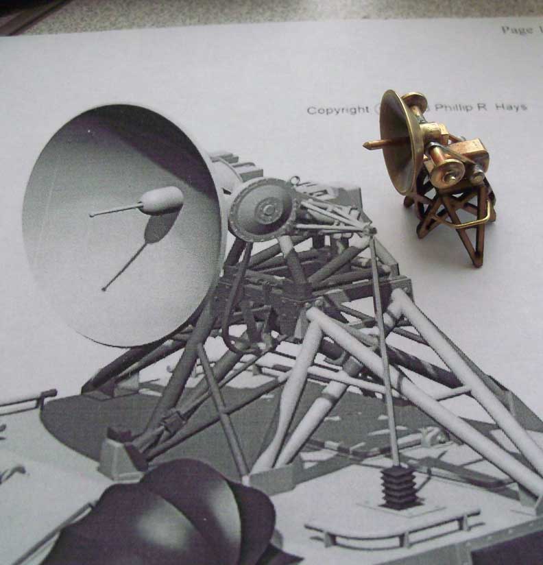
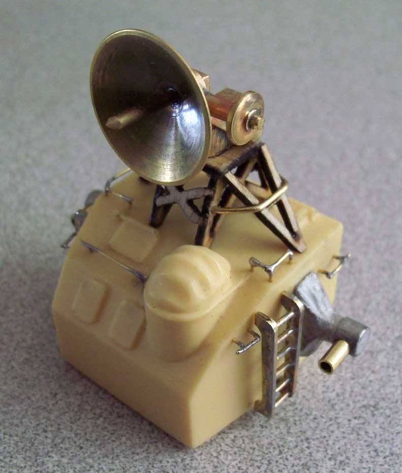
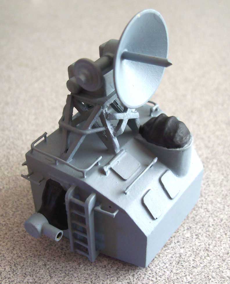
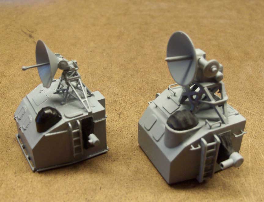
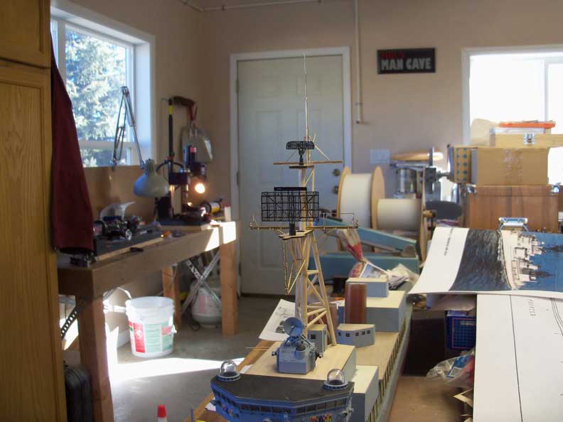
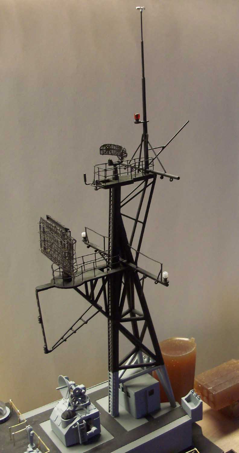
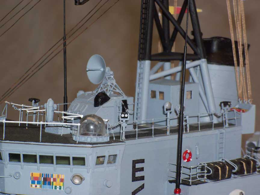
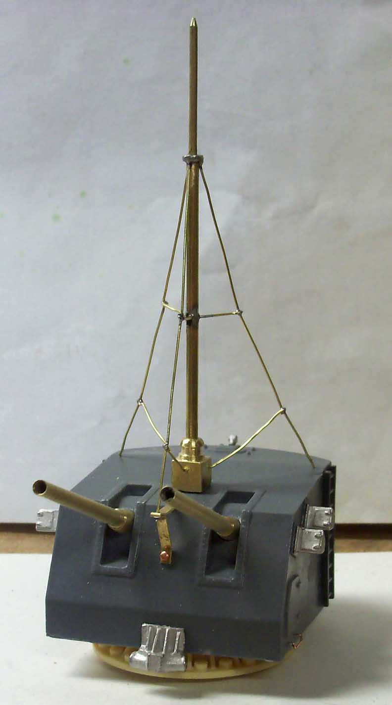
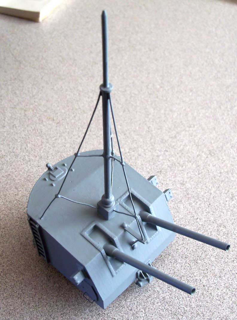
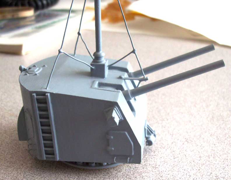
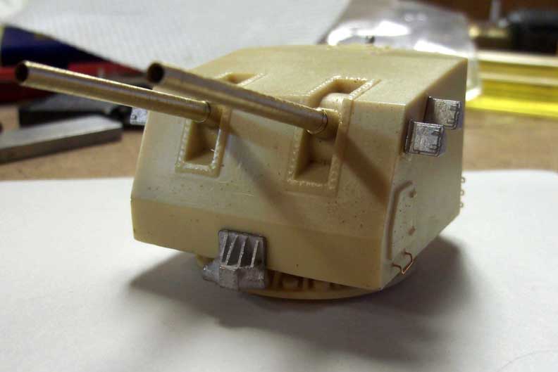
More pictures of the mast. The SPS 10 radar (upper antenna) and
SPS 29 radar (lower antenna).
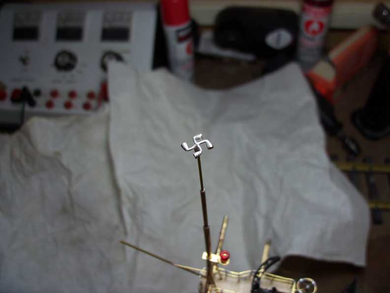
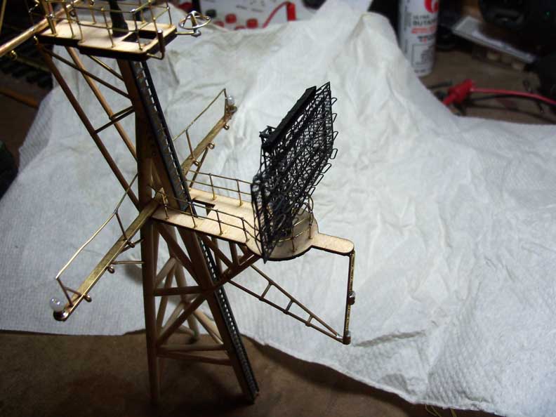
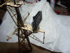
This is the rear mast or ECM mast. ECM standing for Electronic
Counter Measures. I was a sonar technician, not a radio tech so I'm
not 100% sure what all the various antenna's were for. I know some
of the UHF antenna's were for the IFF or Identification, Friend or
Foe. This antenna was 100% scratch built. I sure know why I went to
1:20 scale trains. This is 1:96 scale or smaller than HO scale.
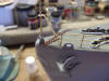
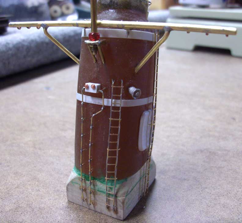
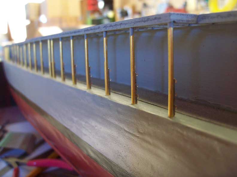
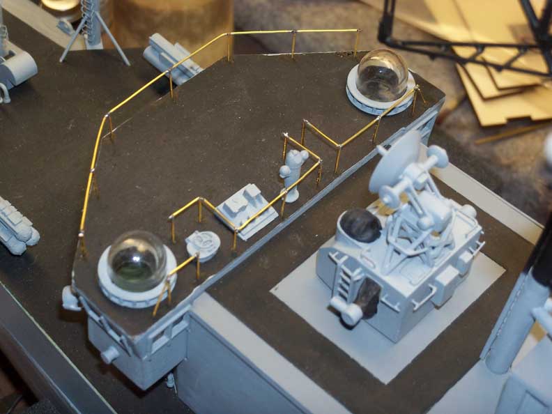
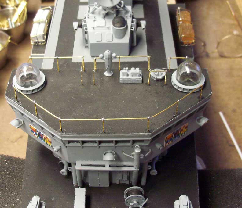
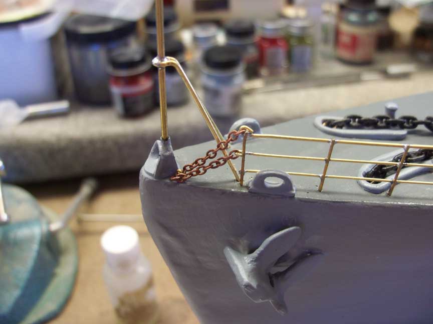
After I built the aft mast, I decided to go back to the bow and
start the final work completing the model from the bow to the stern.
I used etched brass stanchions from John R Haynes. The stanchions are
available in 1, 2 or 3 rail. 3 rail was used on all the main deck. I
used .025" wire for the top rail and .020" wire for the second and
third (bottom) rails. Once placed a micro touch of solder held all
in place. Then they got painted. White on the top rail and gray on
the stanchions, second and third rails.
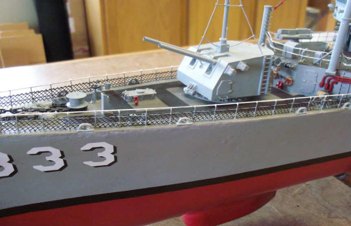
Finished look of the bow
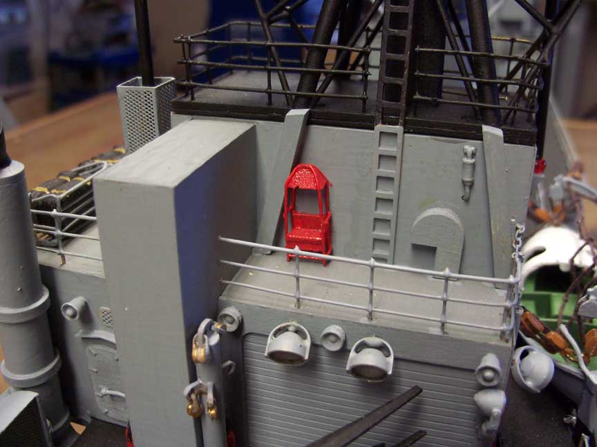
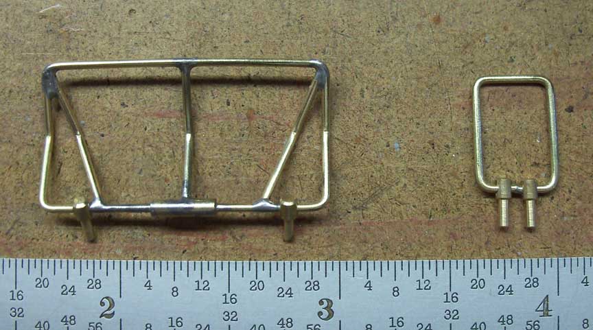
At this point I made contact with the Shapeways designer that made
the MK 32 torpedo tubes. I asked him if he could design more items
for my model which he readily agreed to do. Mark lives in the UK and
severed in the Royal Navy so hardware on the two navy's vary quite a
bit. First up I used his refueling funnels on the torpedo deck
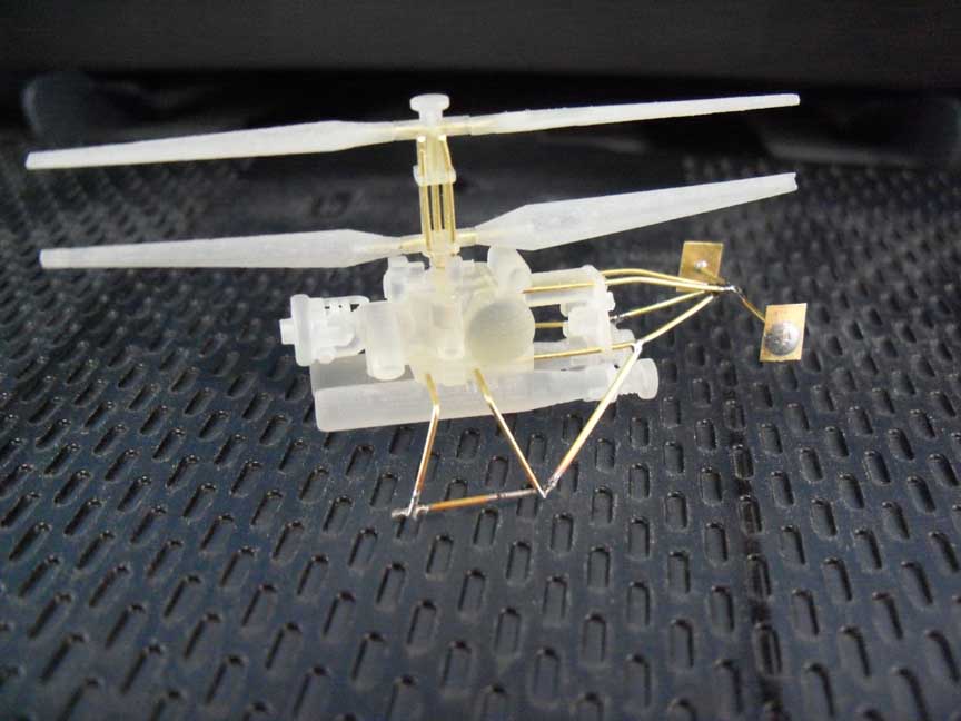
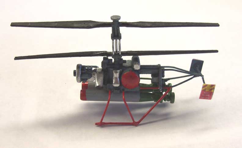
verses mine. I also had him make up the DASH helicopters, The ASROC
launcher, loader and shipping containers. Fire nozzles and
boatswains highline chair. Binoculars and loudspeakers.

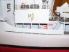
Above is the finished bridge top. The finished CIC roof with the 3D
printed MK 37 fire control direct and binoculars. The signal lights
and some other parts are white metal John R Haynes parts. The rest
are scratch built. The last 3 are of the ASROC deck. The ASROC launcher is the brown resin
casting. This was the one supplied with the BAD kit. Not a terrific
casting. I did replace it with a Scale Shipyard casting and then
again with a 3D Shapeways unit. The forward and aft funnels are set
in place as is the ASROC control booth.
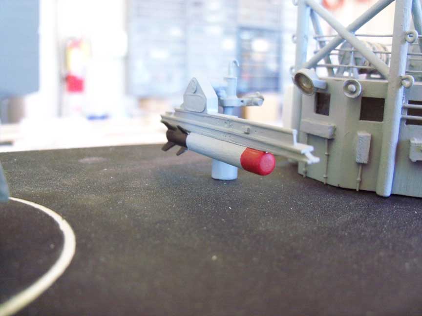
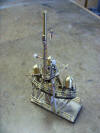
Here is the ASROC loading crane with ASROC torpedo and the Scale
Shipyard ASROC launcher. During loading operations, I was the crane
operator. In the first picture, the white casting is the crane's rail locker
to keep it out of the weather as many of the moving parts were not
painted and would would rust or corrode with salt spray hitting it.


First picture is of the new Shapeways 3D ASROC launcher and loading
crane with missile. Second is the ASROC magazine. Third is of the
top of the ASROC magazine and DASH hanger, forward side. Last is the
Shapeways boatswain chair atop the DASH hanger.


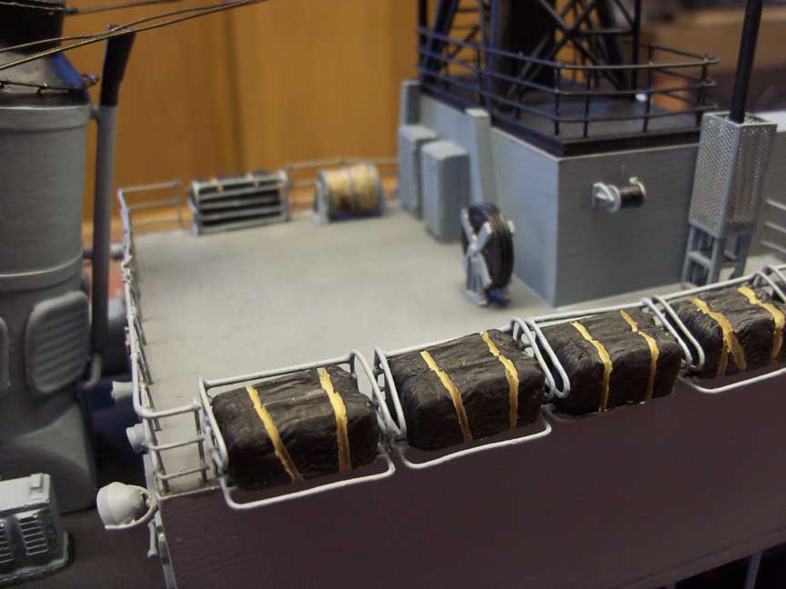
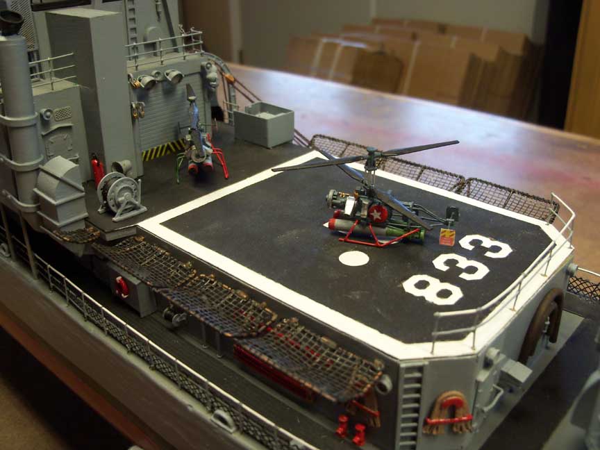
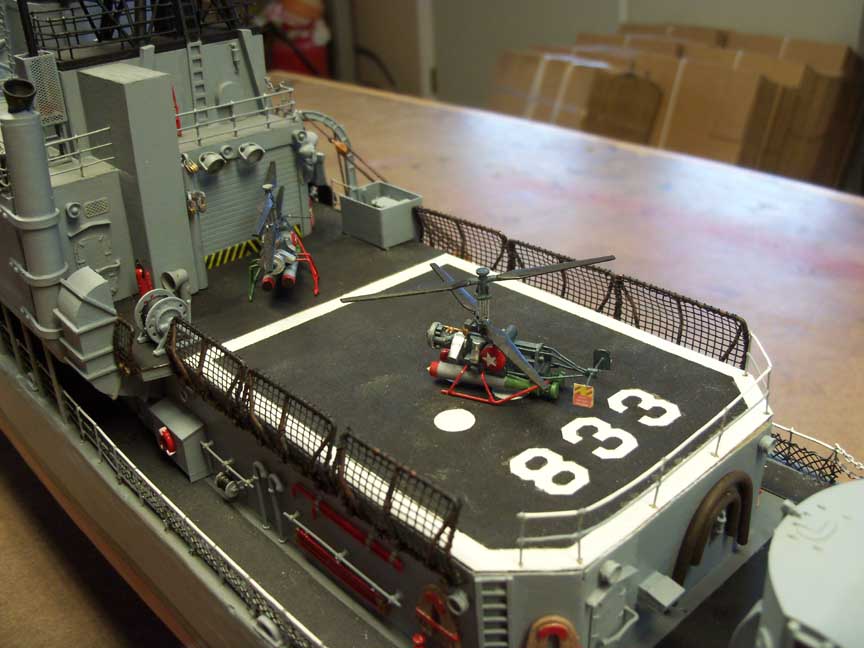
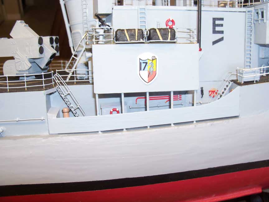
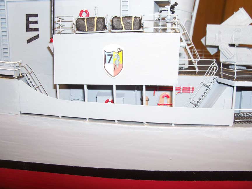
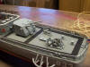
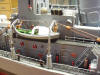
I made the life nets on the helo deck so they could be up or down.
Second picture is with the nets down followed by nets up. Beings the
hull was sealed and under +1 to +2 atmospheric pressures, extra
power to run the air conditioning and purification equipment was
needed. All other Gearing class destroyers used only a large diesel
engine for the electrical generation. On the Thomas, we had a gas
turbine turning our generators. Think of it as a jet engine as it's
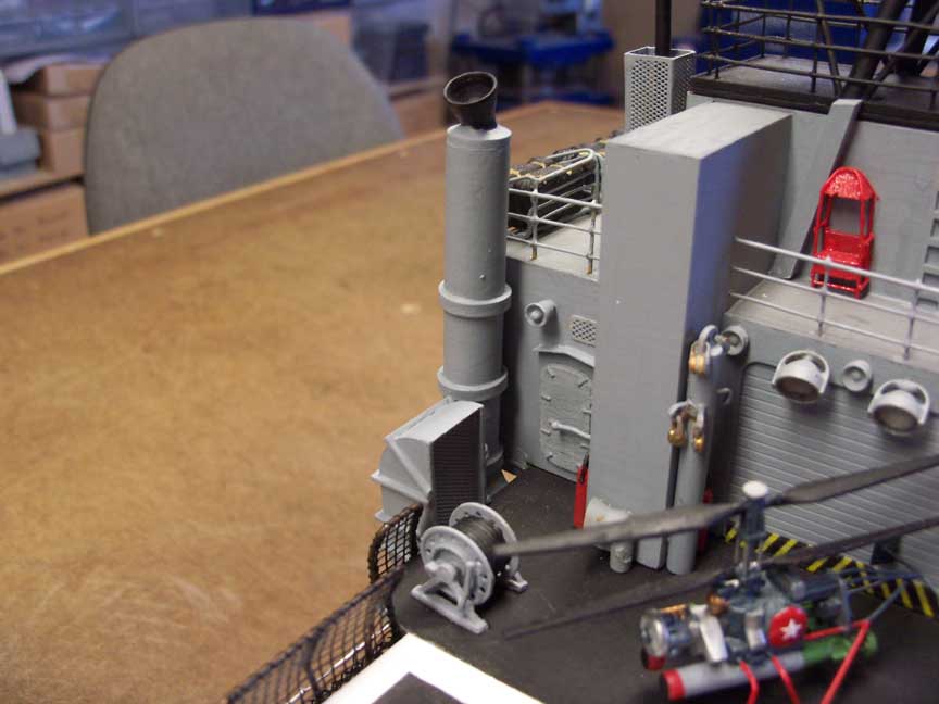
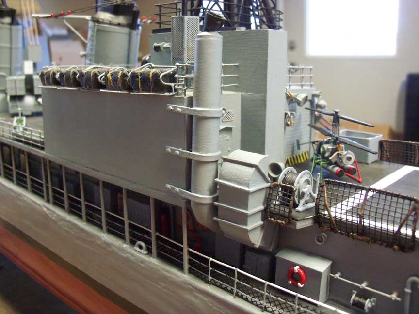
fuel was avgas or aviation gas. The last two pictures show the
intake and exhaust stack for the gas turbine.
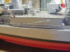
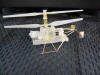
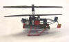
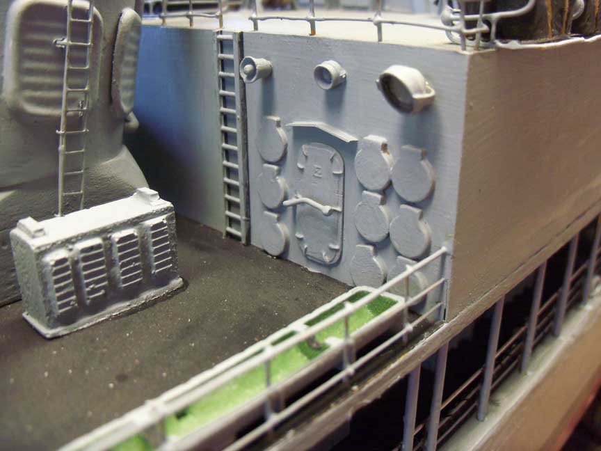
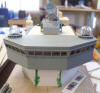
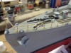
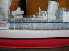
First up is the final finish of the stern, the life boat / motor
whaleboat, the starboard boom and the Shapeways 3D DASH helicopter
assembled and painted. The only shots not pictured so far is the
bulkhead detail along the main deck. That deck consist of the two
wells, one on the port and one starboard, both just aft of the
torpedo deck. Then the long port main deck leading back to the stern
and the starboard deck again leading from ASROC deck to the stern.
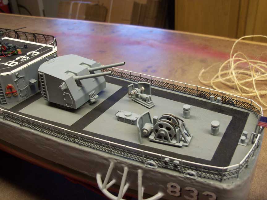
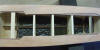
First is the starboard well, then the port well. Next two are the
port side to stern and last, starboard side to stern.
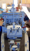
Click the Finished button at the top of the page for a series
of pictures of the finished model. This was a one year project. Lots
of research and pouring over old photo's and cruise books to do the
model right.
On to the next project!!!


 .
.