
![]()
![]()
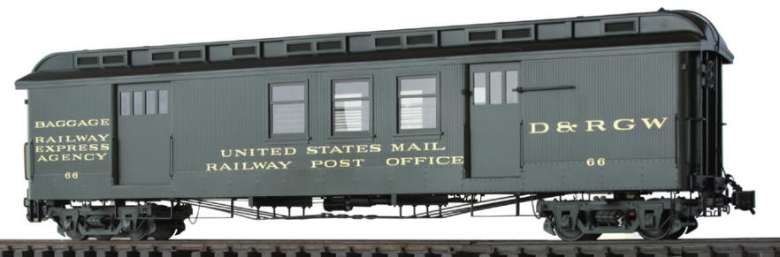
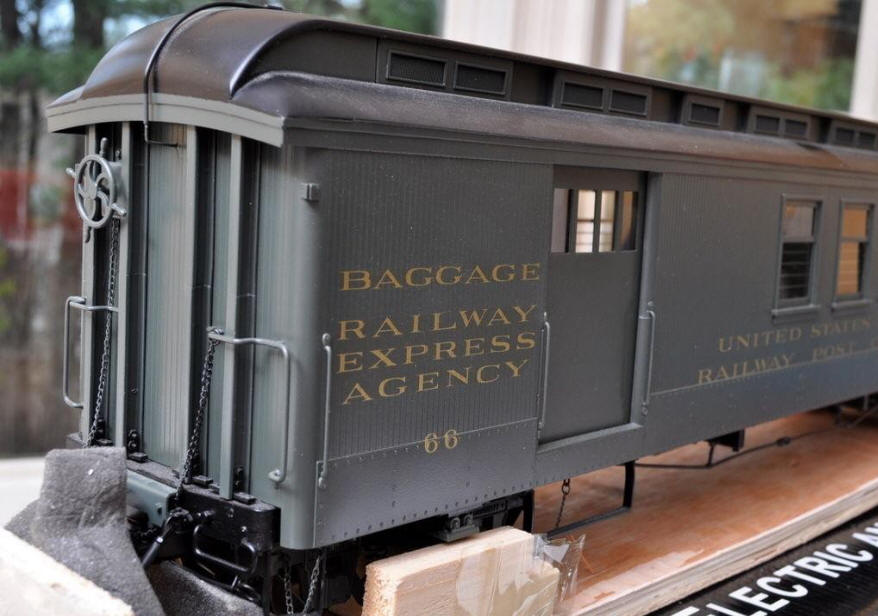
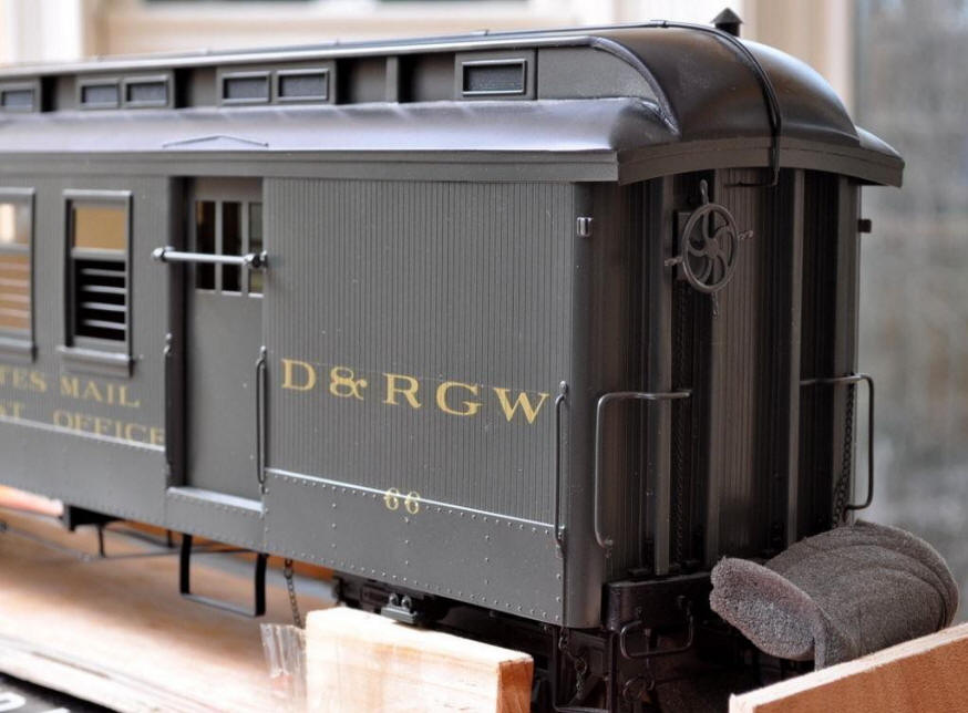
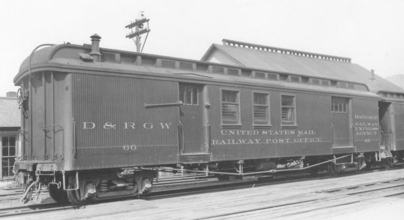
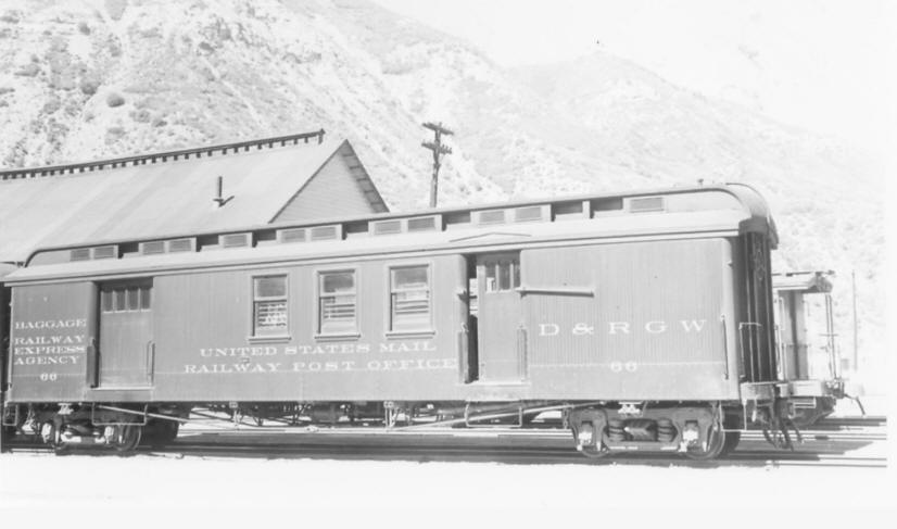
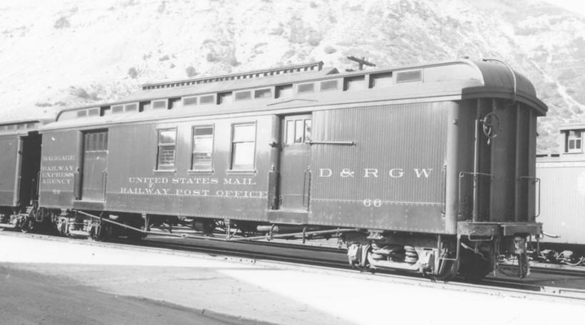
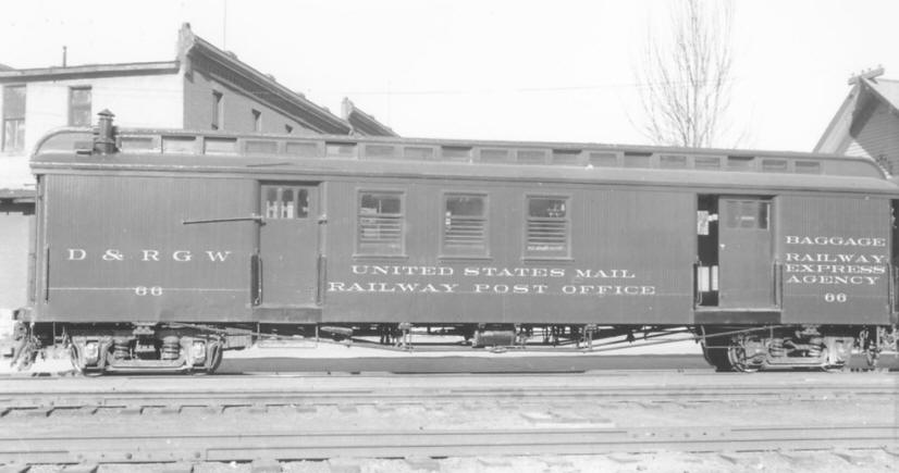
D&RGW RPO #66
Lets start this with pictures of others work. Give us all an idea of where I'm heading. First is a few pictures of Accucraft's version.
A friend has an On3 model which I took a couple pictures of the underbody.
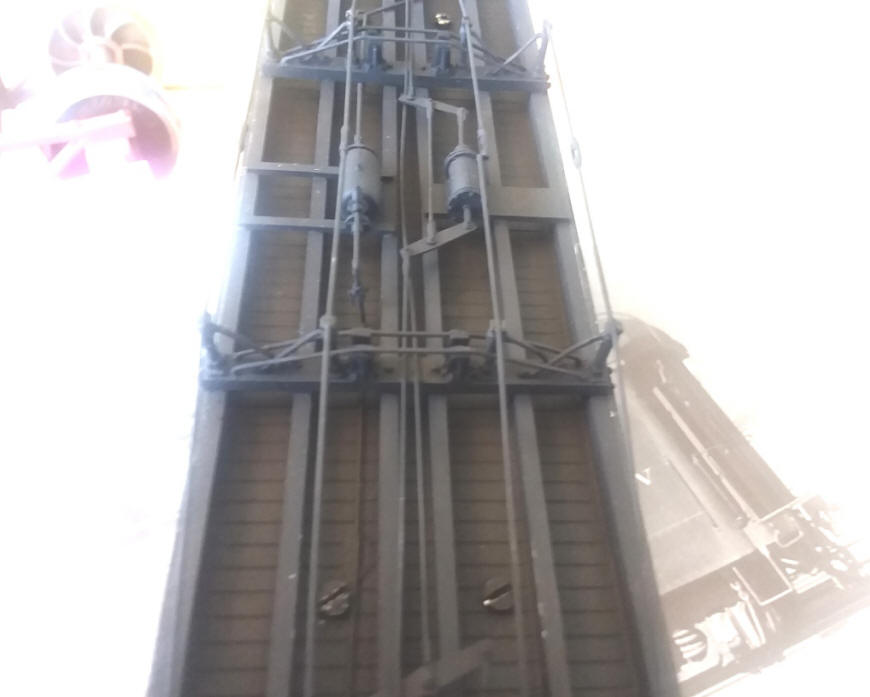
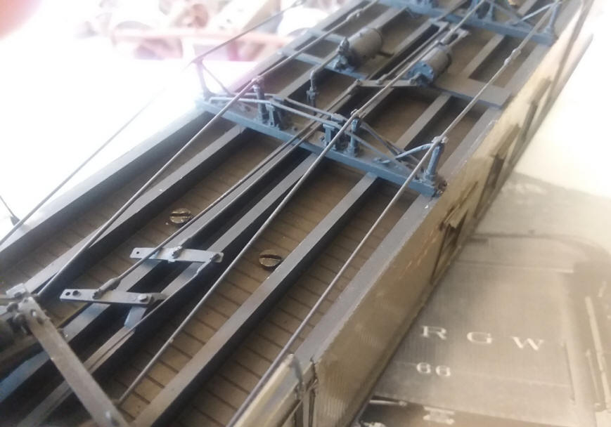
Still doing some research about the underbody. The On3 car is far more detailed than the Accucraft model. If I can verify this bracing, it will be on the kit.
These are some early 3D drawings I made to get an idea of roof ends, car ends and underbody. I have refined the roof and decided it will be a 3D part in the kits.
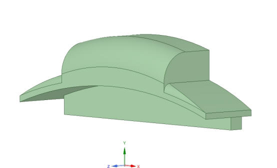
The roof end. Like the short passenger cars, this will be attached to the main roof once built.
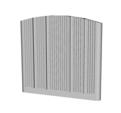
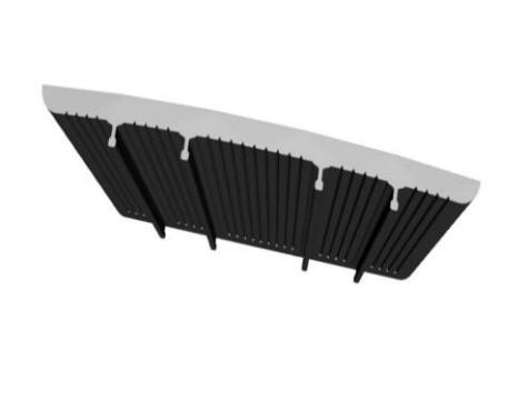
The car end. Kind of hard to see the scribing and rail in the left picture. Right picture shows it off a little better.
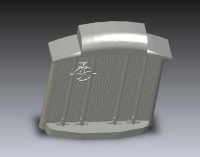
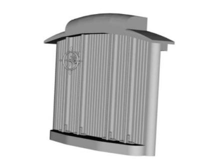
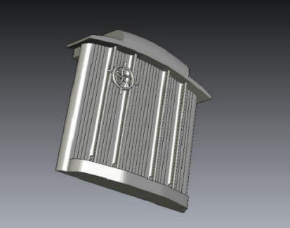
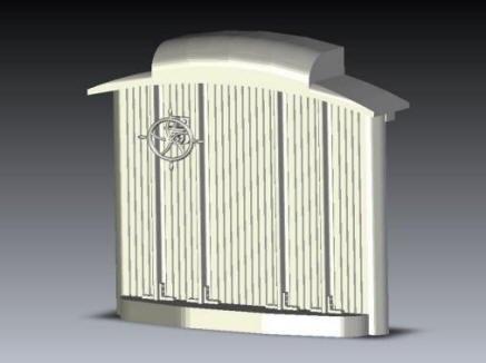
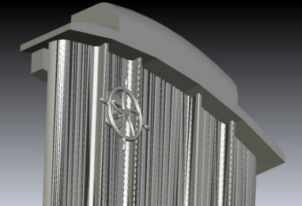
6 different angles of how the end will go together. These are just individual 3D images I pieced together to get an overall rendering. The end beam will be wood. The lock pawl, brake wheel and "L" brackets at the base of the rail will be white metal. The rail will be code 250 aluminum rail and the car ends will be wood.
Next set of pictures is the needle beams with primary queen post and auxiliary queen post. I drew up the sills and needle beams along with truss rods to get an idea of how it's going to look.
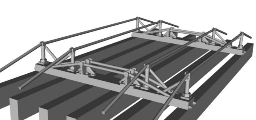
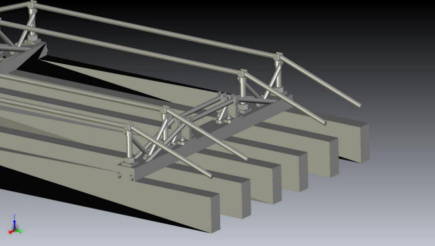
So, this should give you an idea of truss rods and queen post. All the queen post will be white metal with the 1/16" brass rod for truss rods.
And what would the side of the car be without the mail slot?
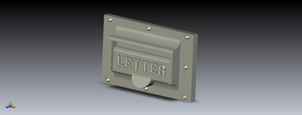
The actual mail slot on the car has raised lettering "LETTER BOX". There are several limitations for lost wax casting with Shapeways. Minimum width and height as well as spacing between letters. All I could get in the space was LETTER. This will be white metal measuring 1/2" tall and 0.7" wide. Both sides. You can see it in these pictures.
Right below the M in MAIL
Below the T in UNITED
Again below the T
Below the M in MAIL
So that's where the kit development is for today. Hope my work is satisfactory. 4-24-2020
6-9-2020 Update
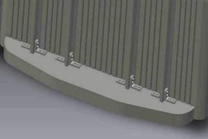
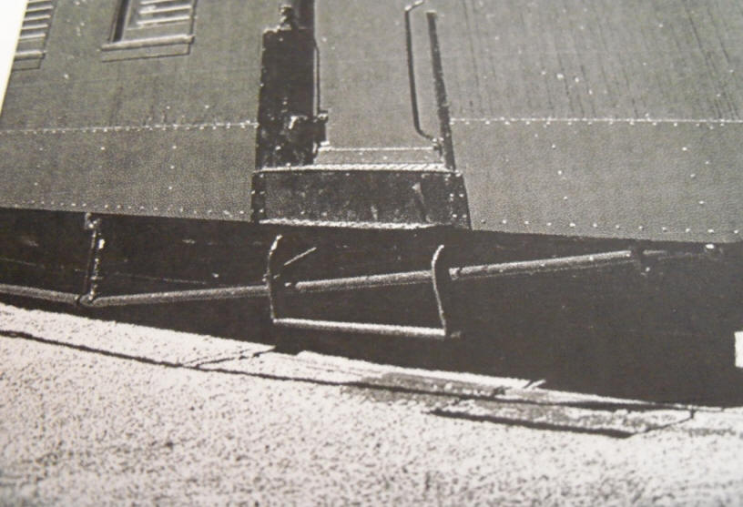
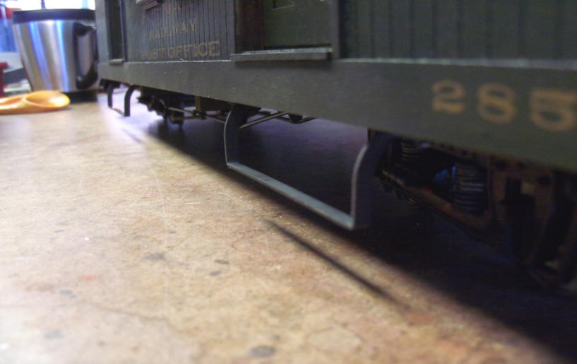
The steps below the baggage and postal doors are rather unique in that they curve out from beneath the sills they are mounted to. This is because the outer queen post are mounted on the needle beam right above the outer sills verses set inside a little. The truss rods block the step legs from dropping vertically from the sill. Here's a picture that captures how the steps curve out.
I have no way to cut brass bar to this shape but I do have access to metal laser cutters that can. So I drew up 2D CAD and uploaded it for cutting.
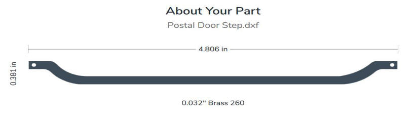
And, 10 days later received this.
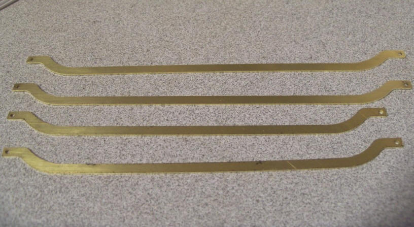
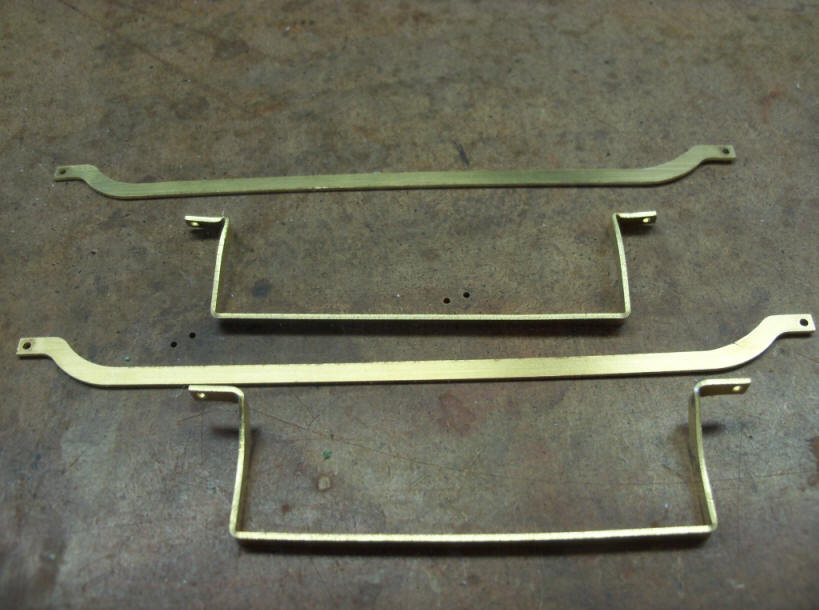
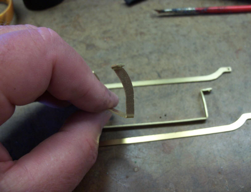
2 lengths. One for the baggage door and one for the postal. Then bent a couple up to test.
I added 4 of them to my short RPO from the previous limited run.
My coffee cup sure finds it's way into many of my pictures!!
That's it for now. The frame jig should be here in the next week so I can start on a prototype of the kit. Stay tooned. Phil
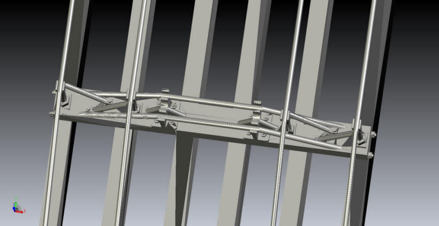
June, 2025
Here's a couple pictures of the first cut of the under frame. I wanted to test fit all the queen post, brake levers and air lines. The truss rods are 1/16" brass rod. All other rofs and air lines are 2.5mm blackened aluminum wire.


